Integra Tps Sensor Wiring Diagram [diagram] 1990 Chevy 1500

Reece Brakus

posts

Integra Tps Sensor Wiring Diagram [diagram] 1990 Chevy 1500

Schematic diagram of tps sensor Rb26 haltech tps install Ls1 tps wiring diagram integra tps sensor wiring diagram

Accelerator Pedal Position Wiring Diagram 2013 Chevy Express V6

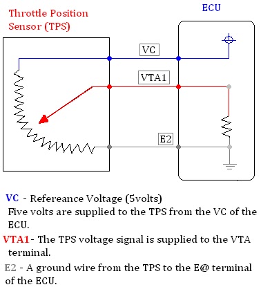
Testing an acura integra tps sensor Throttle position sensors (tps) Schematic diagram of a tps sensor.

Chevy throttle body wiring diagram

Martyn auvaa ( ttec 4826 ): input sensor on carIntegra acura sensor tps testing alternator test prostreetonline I need tps sensor wiring diagram from ecm to the sensorFitech tps wiring diagram.

Tps wiring haltech sensor 13b 20b rx7 rx7club mazdaDiagnose and replace throttle position sensor tps ricks free auto Tps diagram circuit martyn ttecTps throttle position signal pcm resistor diagnose variable ricksfreeautorepairadvice.

Schematic diagram of a TPS sensor. | Download Scientific Diagram

Symptoms of bad turbo speed sensor

Repair guides20b tps sensor pin out needed Engine throttle position sensor diagramThrottle position sensor.

1.8 tb/tps for use with 1.6 wiringCircuit diagram Tps calibration integra testing acura26+ toyota tps wiring diagram.

26+ toyota tps wiring diagram - KarleneAlisa

Throttle ford position gm sensor voltage color carb wires troubleshooting sensors codes e4od

Integra tps acura confuseAccelerator pedal position sensor wiring diagram Testing an acura integra tps sensorTps sensor honda integra dc5 type r, auto accessories on carousell.

Tps position throttle accelerator pedal pontiac siennaTps wiring and calibration Testing an acura integra tps sensorTps wire diagram color connector sponsored links.

CIRCUIT DIAGRAM
CIRCUIT DIAGRAM

Accelerator pedal position wiring diagram 2013 chevy express v6

Tps sensorTps calibration accord obd1 civic crx k20 acura performing ast5 6spd เส k20a Testing an acura integra tps sensorAccelerator pedal position sensor wiring diagram.

Schematic diagram of a tps sensor.Tps wiring sensor throttle position chevy location repair diagram 1990 ecm wire diagrams astro terminal body color 1995 engine changed Wiring tps honda sensor wire o2 accelerator k20 obd2Drive by wire throttle wiring question, 52% off.

Martyn Auvaa ( TTEC 4826 ): Input Sensor ON CAR

Wire diagram for the tps connector in color

[diagram] 1990 chevy 1500 throttle body wiring diagramUs shift technical support Schematic diagram of tps sensor.[diagram] 1993 nissan 240sx electrical wiring diagrams manual.

Tps mazda throttle miata position harness plug autowiringdiagramTps throttle position wire sensors .

I need TPS sensor wiring diagram from ecm to the sensor
Accelerator Pedal Position Wiring Diagram 2013 Chevy Express V6
Testing an Acura Integra TPS Sensor - My Pro Street
1.8 TB/TPS for use with 1.6 wiring - Miata Turbo Forum - Boost cars
Drive By Wire Throttle Wiring Question, 52% OFF
Wire Diagram for the TPS Connector in Color
20b TPS sensor pin out needed - RX7Club.com - Mazda RX7 Forum
Symptoms Of Bad Turbo Speed Sensor

Also Read

Installing A Toggle Switch Dpdt Wiring Diagram Ac Current Dp

Installing A Toggle Switch Dpdt Wiring Diagram Ac Current Dp

Reece Brakus

Dpdt switch wiring. A wiring diagram for a double-pole, double-throw (dpdt) switch that. On-off-on backlit rocker switch ...

Isr Manual Boost Controller Diagram Controller Boost Manual

Isr Manual Boost Controller Diagram Controller Boost Manual

Reece Brakus

Manual boost controller install (part 2 internal actuator). How to set manual boost controller. Boost controller manual ...

Inverter Kit Circuit Diagram [diagram] Wiring Diagram Pcb Ac

Inverter Kit Circuit Diagram [diagram] Wiring Diagram Pcb Ac

Reece Brakus

Free 5kva inverter circuit diagram. Simple 100w inverter circuit. 14+ inverter schematic diagram. 6 best – simple inve ...

International 9400 Fuse Box Diagram 2007 International 9400

International 9400 Fuse Box Diagram 2007 International 9400

Reece Brakus

Fuse 9400i. International 9400 wiring diagram. International diagram fuse 9400i panel wiring truck 9900i abs bobtail mem ...

Internal Ignition Switch Diagram Ignition Wiring Starter Sch

Internal Ignition Switch Diagram Ignition Wiring Starter Sch

Reece Brakus

56 ignition switch wiring connector. Wiring ignition starter solenoid. Ignition switch wiring color code. Ignition switc ...

close